






| Reference Photos | Feature | Recommended | Description |
 |
Wall Thickness |
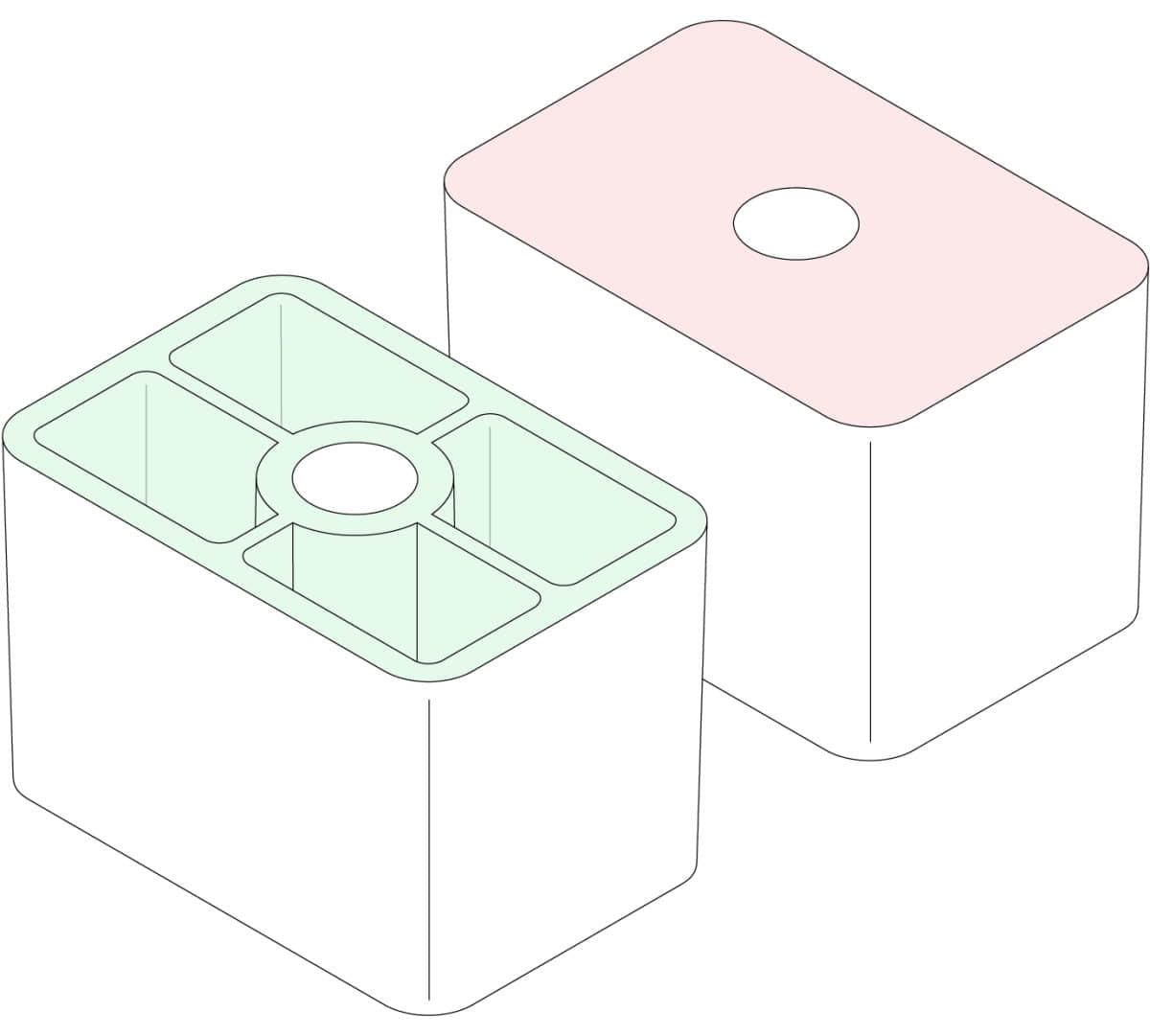
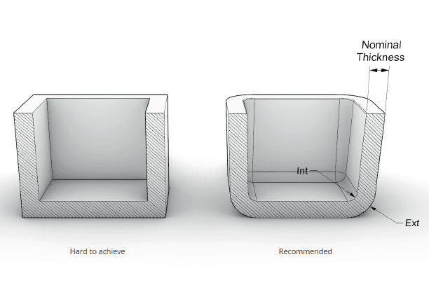
The recommended wall thickness of injection molded parts is 1-3mm and should be as uniform as possible
|
Plastic products with normal wall thickness save material, have uniform cooling, few molding defects and low cost.
1. If the wall thickness is too thin (less than 1mm), it will cause difficulty in molding. If the wall thickness is too thick (more than 3mm), there will be a risk of shrinkage.
2. Plastic products with uniform wall thickness will reduce warpage caused by internal stress during molding, and shrink evenly without shrinkage defects.
|
 |
Ribs |
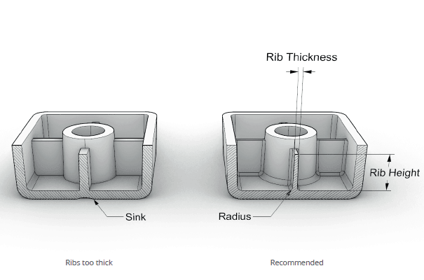
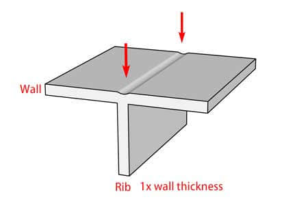
Typically, wall thickness is approximately 50%-75% of nominal wall thickness. To minimize the sinking of excessively thick sections at the intersection of ribs and walls. The bottom of the ribs must also be rounded. This fillet radius should be close to 0.25T-0.5T, where T is the nominal wall thickness.
|
Injection ribs are used to increase the structural integrity of a part and improve its load-bearing capacity. When placing ribs, fully consider the fluidity of the plastic and the thickness and depth of the ribs. If it is too thick, it will easily shrink, and if it is too deep, there will be a risk of stripping. Shallow ribs are easy to fill and there are no problems with ejection.
|
 |
Radius |
We recommend that the inner and outer radii be equal and at least equal to the wall thickness.
|
Sharp corners can widen flow paths, change direction, increase internal stress concentrations, and potentially cause plastic parts to fail. Rounded corners can reduce internal stress concentration and prevent breakage.
|
 |
Draft Angle |
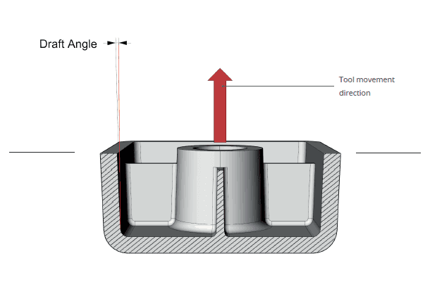
Generally, the draft is between 1-3 degrees. An appropriate draft angle will increase the quality of the part and shorten the molding cycle.
|
When a part needs to be ejected from the mold, without draft, after the part cools and shrinks, it will grab the vertical wall, which requires more force to push it out. It maybe cause a number of defects, including ejection punch marks or drag marks where the material rubs against the mold.
|
 |
Undercut |
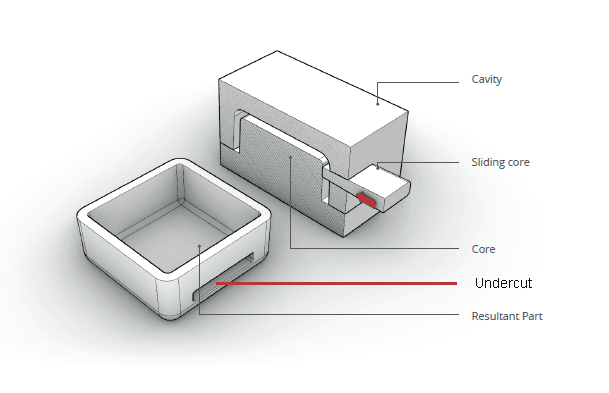
We recommend eliminating undercuts from the design. But if they have to be used, a slide or lifter must be installed in the tooling. Slides are used to release external undercuts and lifters are used to release internal undercuts
|
Grooves, notches, embossed text, and logos may interfere with normal stripping of injection molding toolings. The size and location of the undercut determines the structural complexity of the mold. The larger the undercut, the more complex, the greater the quantity, and the higher the mold cost.
|
 |
Shrinkage |
Different materials have different shrinkage, ranging from 3% to 10%. The mold must be designed according to the molding material.
|
Shrinkage refers to the dimensional change of injection molded parts when they are cooled. Mold Designers must consider the impact of the shrinkage rate of the injection material on the shape, appearance, and size of the part.
|
 |
Lifter |
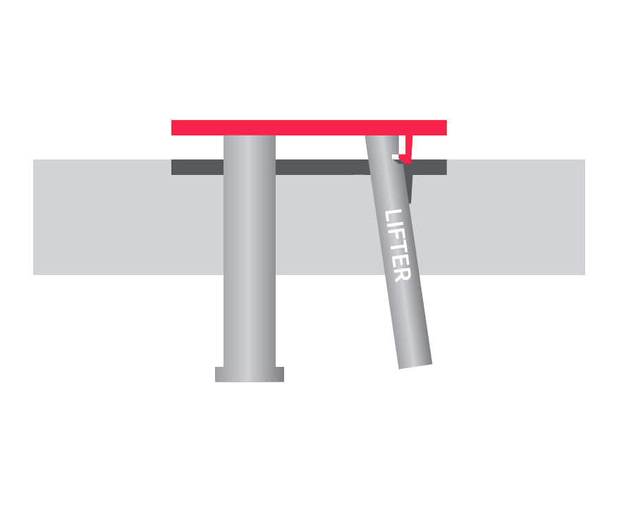
Lifts are used to release internal undercuts, grooves or protrusions on the interior surface of a part.
|
The lifter and the ejection pin are ejected at the same time, but the lifter is ejected at a certain angle, so when the ejection pin pushes the part out, the lifter moves outward and away from the feature, allowing the part to be removed smoothly.
|
 |
Slider |
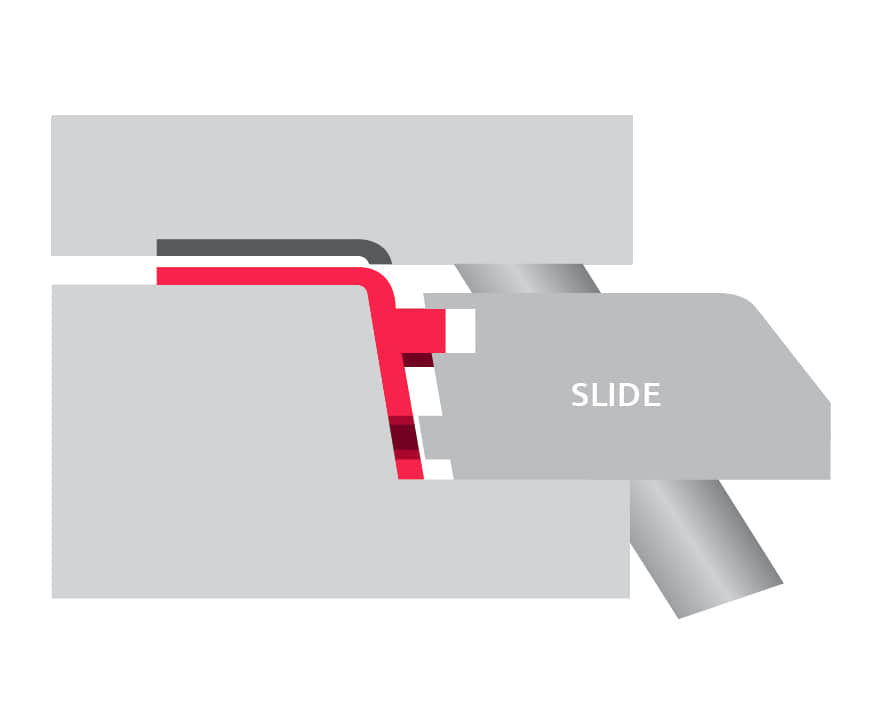
The slide releases external undercuts, depressions, or protrusions on the exterior surface of the part.
|
Injection molding sliders usually consist of a guide pin, slider body, forming surface, press block, wear plate, and wedge. While the mold is opening, the guide pin and slider body move laterally away from the part, and the ejector pin pushes out the product, completing the injection molding.
|
 |
Unscrewing |
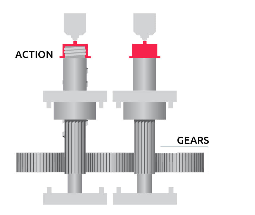
The locking mechanism should be robust to prevent accidental core loosening during injection. Thermal conduction and cooling for rotating cores should be considered.
|
Injection mold unscrewing is designing undercuts and side cores to be rotatable via motors so that molded threaded plastic parts can be unscrewed and released from the cores, enabling demolding of the parts after injection.
|
 |
Collapsible core |
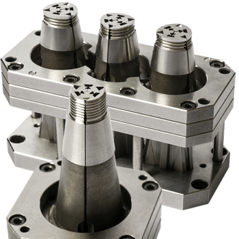
The sliding core material has adequate strength and rigidity. The inner core should be properly lubricated with the surrounding movable sliders.
|
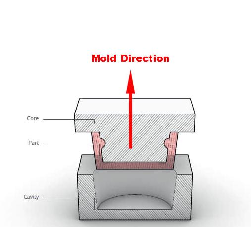
A collapsible core is an interior mold component that can be expanded to support interior cavities when injection molding, then contracted to provide clearance for part stripping.
|
 |
Bump off |
1. Plastic must be flexible enough to expand and deform.
2. The undercut must have a lead angle of 30o to 45odegrees.
3. The undercut must smooth, no corner and ribs.
|
The principle of bump off is to use the plastic to deform and release from the mold when it pops up. It's often used to create threads in bottle caps.
|
 |
Bosses |
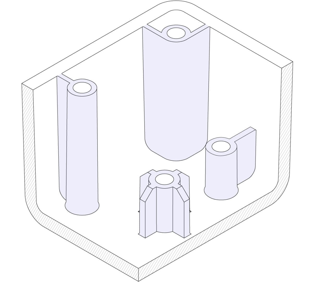
1. Avoid direct connection between boss and main wall
2. Support bosses with ribs or connect them to a main wall
3. For insert bosses, the outer diameter is twice insert’s nominal size
|
A boss is a raised area used to fasten and connect parts. They consist of cylindrical protrusions and ribs with holes designed to accommodate screws, threaded inserts, or other types of fastening and assembly hardware.
|
 |
Insert |
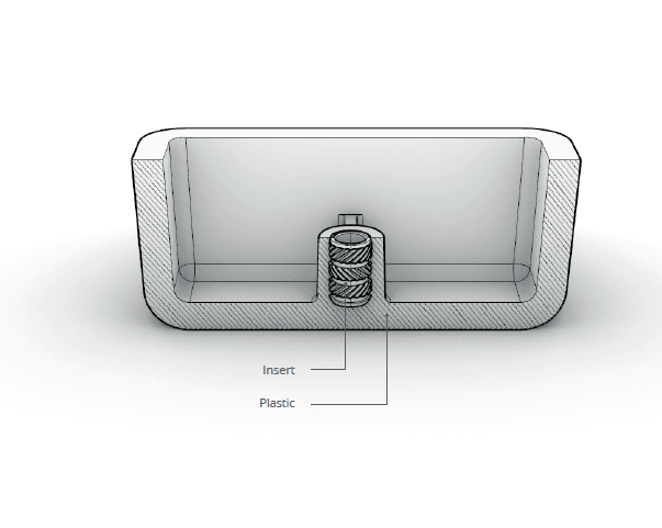
Theer are 3 common types of insert for thermoplastics:
1. Ultrasonic welding
2. Thermal Insertion
3. Insert Molding
|
No matter which solution is used, there are advantages and disadvantages.
1. low residual stress is low cost solution, low residual stress.
2. Thermal Insertion is low cost solution, less suitable for volume manufacture.
3. insert Molding high quality parts, but also is high cost, suitable for large volumes productions. |






| Item | Methods |
| Part design | A excellent part design reduces mold complexity and reduces costs. |
| Part design | Paying attention to surface treatment from the beginning is the key to the success of the part. Once the surface finishes is decided, it can't be changed or the cost of change is high. |
| Order volume | The number of mold cavities is determined by the expected order quantity. The greater the number of cavities, the higher the production capacity. However, the greater the number of cavities, the greater the difficulty and the higher the cost. |
| Part size | The larger the part, the more material is required. The more materials, the higher the cost. |
| Side action | Commonly used mold side activities include lifter, slide, unscrewing, collapsible core, bump off etc. No matter what structure is used, it is only to make high-quality and reliable molds. Which mold structure to choose is determined by the specific product structure, the number of mold cavities and the budgeted cost, and needs to be balanced between them. |
| Production Cycle | A good cooling system and precise molds are common ways to speed up the production cycle, but both will increase costs and need to be balanced between time and cost. |
| Tolerance | For plastic products with tolerance requirements, maintaining tight tolerances during mold production is the key method to control dimensions. The smaller the tolerance, the greater the difficulty and the higher the cost. |
| Cooling time | The temperature of the injection mold is a key factor that determines the length of the entire molding time. By uniformly cooling the mold cavity, the production cycle can be accelerated and efficiency maximized. Cooling time differences can profoundly affect the mold manufacturing process. |
| Mold Material | There are thousands of mold materials. Choosing the correct mold steel according to part requirements will not only reduce costs, but also increase mold life. This is one of the important ways to improve competitiveness. |
| Gate | Gate location, type, and quantity have a direct impact on part molding. According to the product structure and design requirements, scientific design of the mold is the best way to reduce costs. The traditional cold runner is low-cost. The hot runner system will increase the price of the mold, but it will also increase the beauty of the parts and improve competitiveness. |
| Part material | Generally, if there are no special requirements, cheap materials will be chosen, such as PP, PE, etc. But for products with performance requirements plastic parts, engineering plastics are the first choice, such as ABS, PC, NYLON, etc. High-temperature materials are the first choice for products with special performance requirements, such as PEEK, PEI, PAI, PPS, LCP, etc. The higher the requirements, the higher the price. |


Yes, rapid prototyping and 3D printing can help customers solve potential defects, we have more than 10 year experience in this field.
Yes, in order to be able to automate the injection molding production, we design the relevant aspects from the beginning, from mold design to the matching of automatic fixtures.
Depending on the complexity of the mold, it is generally completed within 3-7 days.
DFM stands for Design for Manufacturability. It refers to a design methodology that helps ensure new parts and products are designed with manufacturing/producibility in mind from the very beginning.
The goals of DFM are to optimize designs to be easier and less costly to produce, while meeting functional and performance requirements. It aims to reduce manufacturing costs, improve quality, shorten product development cycles and simplify the production process through close collaboration between design and manufacturing teams.
Some key principles of DFM include designing parts with minimal assemblies, using standard sizes/components when possible, avoiding complex or tight tolerances, considering tool/fixture access and material flow etc. DFM ensures a smooth transition from design to mass production and helps gain advantages such as increased throughput, lower scrap rates and improved overall production efficiency.