The Most Detailed Injection Molding Defects and Solutions (2025)
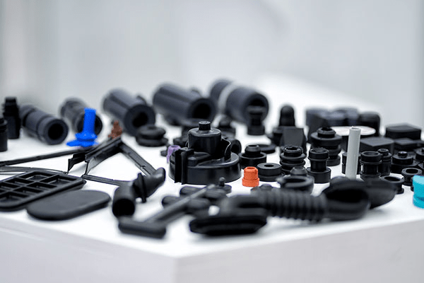
Injection molding is a process for manufacturing plastic products on a large scale. Since this process involves many steps, many different injection molding defects will occur. Injection molding defects can reduce the cosmetic appeal and structural integrity of injection molded parts and even affect functionality. The causes of defects may involve mold design, mold materials, tolerances, product materials, injection molding processes, etc.
This article will introduce in detail the types of defects in injection molding, their causes, and corresponding solutions to better help everyone produce high-quality plastic products.
1. Weld lines (knit lines)
Weld lines are defects that occur when two flows of molten plastic fail to fuse completely during injection molding.
")
Potential causes of weld lines include:
- Insufficient injection pressure – Low pressure impedes melt flow around obstacles in the mold cavity.
- Low melt temperature – Cooling of melt before it fully packs leads to early solidification in some cavity regions.
- Injection speed too slow – Slow flow causes uneven cooling as melt reaches far cavity areas later than others.
- Excessive melt volume – Large shot size slows overall flow rate hampering proper fill.
- Mold design issues – Improper gate placement or thin walls affect flow/packing
Solutions (Prevention):
- Increase injection pressure to fuse flows fully
- Add hot runners to maintain consistent melt temperature
- Redesign mold with optimized gates location/number to promote smooth fill
- Select resin with better mold flowability properties
- Use mold temperature to increase melt material fluidity
2. Warpage
Warpage refers to non-uniform shrinkage across a molded part that results in distortions, bends or surface irregularities.
")
Potential causes of weld lines include:
- Rapid or uneven cooling – Faster cooling rates lead to internal residual stresses as outer layers shrink away from core before it fully solidifies.
- Overheating – Excessive heat during injection causes uneven shrinkage upon cooling.
- Low thermal conductivity – Materials like engineering thermoplastics dissipate heat slowly causing inner warp.
- Mold design – Thicknesses that vary sharply or asymmetry induce more warping due to proportional shrinkage rates.
- Uneven wall thickness – Inconsistent shrinkage of different wall thicknesses leads to warping deformation.
Solutions (Prevention):
- Gradual cooling – Slowing cooling rates using wider temperature windows and vents allows for uniform shrinkage.
- Optimized gate placement – Prevent temperature gradients with properly located gates.
- Hot runner systems – Maintain consistent melt temperature throughout fill.
- Uniform wall thickness – When designing parts, try to make the wall thickness of the part as uniform as possible.
- Change to crystalline resins – Semicrystalline grades shrink more predictably than amorphous.
- Use of filler resin – Filled polymers exhibited reduced warping vs unfilled.
- Mold balancing – Analyze shrinkage profile using FEA for balanced mold textures/vents.
3. Jetting
Jetting is an injection molding defect that appears as snake-like or wavy patterns on the surface of molded parts. It occurs when the resin flows too fast through gates or other restricted flow areas into the mold cavity.
")
Potential causes of weld lines include:
- Resin Flow Pattern: When the resin squirts back and forth through the gate in oscillating jets, instead of smoothly filling the cavity. This forms streaky flow patterns that lead to jets.
- Injection speed: Excessive injection speed forces the melt into the mold too quickly before it has time to fully pack out. The rapid drop in velocity as it enters the cavity causes jet-like streams.
- Resin temperature: If resin is too cold, its higher viscosity inhibits proper melt packing before solidifying into jets.
- Gate Design: Improper gate size, location or number of gates can cause the melt to impact the cavity wall instead of entering gently.
- Runner/Sprue Design: Long or convoluted runners increase flow resistance and chances of jetting due to uneven fill patterns.
- Mold temperature difference is too large: If the temperature difference between different areas of the mold is too large, it will lead to different filling speeds, uneven backflow and cooling rates, and formation of jets. Temperature control needs to be strengthened to keep the difference within 2°C.
The root cause of squirting is related to one or more of the following:
- How molten plastic flows in the mold
- Injection speed
- Melt temperature
Solutions (Prevention):
- Gate design – Optimize gate size, location and number of gates to introduce melt gently into cavity center without sharp redirects.
- Injection velocity – Slow injection speed gradually through dynamic control to match filling pattern. Slower fill speeds allow polymer chains to stay mobile longer for better weld lines elimination.
- Mold temperature – Higher cavity temperature help resin maintain flowability for improved packing. Use narrow temperature window of ±1-2°C.
- Optimize Runner structure – Minimize flow distance and redirects from sprue/runners to gate for more pressure maintenance. Simplify the flow channel, reduce the bending arc and angle, reduce the flow speed and change the possibility of flow direction. Appropriately increasing the flow channel cross-sectional area is also beneficial to flow.
- Process optimization – Adjust packing pressure and time along with other molding parameters through experimentation.
- Choose a resin with lower viscosity and better fluidity – Low viscosity resin can easily solve the injection problem, but it may affect the mechanical properties, so a good balance point needs to be chosen.
4. Flow Lines
Flow lines refer to the tracks left on the surface of the product during the flow of molten plastic. They can also manifest as ring-shaped bands near inlet points on part surfaces. While flow markings typically do not affect component integrity, they are undesirable for products that demand aesthetic appeal. The main reason for flow lines is that the melt cools and solidifies at different speeds. Therefore, such defects are particularly likely to appear on the surface of thick-walled plastic parts.
")
Causes of flow lines:
- Variations in melt flow velocity – Differences in cooling rates as material flows multidirectionally in the mold.
- Non-uniform wall thickness – Inconsistent thickness leads to uneven cooling and solidification speeds.
- Slow filling or low pressures – Excessive melt dwell time induce unnecessary flow patterns.
Solutions (Prevention):
- Full pack of the cavity before cooling – Achieved by raising injection pressure, speed and melt temperature to optimal levels.
- Smoothening of thickness transitions – Rounding sharp corners and edges avoids abrupt flow/velocity changes.
- Strategic gate placemen t– Locate gates away from vents to prevent premature resin solidification during flow.
- Uniform cooling design – Ensuring even melt temperature distribution via balanced mold textures/coolant channels.
- Process optimization – Fine-tuning variable settings through experimentation to eliminate temperature gradients.
5. Short shot
Short shot is a defect where the injected plastic fails to fully fill the mold cavity. It is one of the most serious molding defects as it can drastically alter the desired appearance or functionality of the molded part.
")
Causes of short shot:
- Inadequate shot size – Shot weight is not enough to fill all cavities due to improper injection calibration.
- High melt viscosity – Thick melt solidifies before fully packing out if held in the barrel too long above melting point.
- Entrapped air – Compression of air in poorly vented cavities prevents displacement by inbound melt front.
- Mold venting issues – Residual air unable to escape cavities due to insufficient venting system.
Solutions:
- Optimization of gate and runner geometry – Wider, fewer restrictions on melt flow path into cavities.
- Increase of injection speed/pressure – Within the limits of the machine to help the melt flow and fill the entire cavity.
- Ensuring uniform melt temperature – Neither too cool nor hot to induce defects.
- Higher mold temperature – Keeps melt flowing for longer packing time before freeze off.
- Improved venting system – Removes air rapidly through increased vent size/number.
- Use of lower viscosity resin – Eases filling of difficult to reach areas.
6. Shrinkage (Sink Mark)
Sink marks refer to small depressions or dimples that appear on thicker, flat surfaces of molded parts. Sink marks mainly occur in thicker areas since they take longer to solidify compared to thinner cross-sections.
")
Causes of sink marks:
- Inadequate cooling time – Insufficient time for thicker sections to solidify leads to internal shrinkage.
- Deficiency in cooling mechanism – Premature melting or non-uniform temperature distribution results in uneven shrinkage.
- Insufficient packing pressure – Low cavity pressure cannot completely fill voids left by shrinkage.
- Excessive gate temperature – Rapid heat dissipation from gate cools outer skin faster than interior.
Prevention measures:
- Increased cooling time – Allowing more time reduces residual stresses from differential shrinkage.
- Optimized wall thickness – Thinner walls decrease cooling time differential between sections.
- Lower mold temperature – Ensures uniform melt solidification front propagation.
- Higher packing pressure – Fully compacts melt before solidification setting in.
- Extended pressure hold – Adequate time under pressure helps evacuate air traps.
- Balanced gate locations – Prevent premature solidification around poorly placed gates.
7. Air Traps (Burn Marks)
Burn marks refer to black or rust colored discoloration that appears on the surfaces or edges of molded parts. Like flow marks, burn marks generally do not compromise part integrity but can become an issue if degradation occurs.
")
Causes of burn marks:
- Residual air entrapment – Trapped bubbles in melt undergo localized overheating.
- Excessive melt temperatures – Material is overheated due to high shear/residence time.
- Fast injection speeds – Insufficient time for air purge before freeze-off.
Prevention of burn marks:
- Lower melt and mold temperatures – Prevents thermal degradation of polymers.
- Slowed injection velocity – Allows trapped air pockets to vent before onset of packing.
- Optimized gate and vent design – Targeted vent placement efficiently removes air.
- Ventilation improvements – Wider, more numerous vents expel air without restrictions.
- Shortened molding cycle – Less time for material or air to overheat under shear/pressure.
- Control injection profiling – Gradual metering filling avoids concentrate stresses
8. Wrinkling
Wrinkling refers to rippled or folded appearance on molded part surfaces caused by uneven shrinkage during part consolidation and ejection.
")
Causes of wrinkling:
- Rapid melt cooling – Outer skin sets before inner core causing differential shrinkage strains.
- Non-uniform wall thickness – Thin cross-sections cool unevenly relative to thicker areas.
- Encapsulated air – Trapped bubbles collapse on cooling, imparting local stresses.
- Stiff inserts – Integrated components restrict shrinkage leading to surface folds.
- Excessive pack/hold pressures – Over-compaction causes plastic yielding on ejection.
Prevention measures:
- Optimized cooling curves – Gradual controlled reduction in melt temperature.
- Uniform wall thickness design – Consistent radial heat dissipation profiles.
- Venting enhancement – Timely air removal via additional vents/slits.
- Flexible inserts – Conformable designs freely release during shrinkage.
- Modified pack profile – Minimal sufficient pressure to fully consolidate.
- Mold lubrication & release agents – Smooth ejection without surface adhesion.
- Post-molding annealing – Heat treatment relaxes internal stresses.
- Adjust injection molding process parameters – According to the specific plastic raw materials and mold design, adjust process parameters such as temperature, pressure, speed and cooling time during the injection molding process to obtain the best filling and cooling effects.
- Improve mold design – Optimize the cavity design of the mold to ensure that the shrinkage stress of the plastic is evenly distributed during the cooling process. At the same time, the exhaust system design of the mold is improved to ensure that air can be discharged smoothly and avoid the formation of bubbles and wrinkles.
- Optimize material selection – Choose plastic materials with lower shrinkage, good fluidity and thermal stability to reduce the occurrence of wrinkles.
9. Ejector Marks
Ejector marks refers to indentations or scratches left on molded parts during the ejection process from the mold.
")
Causes of ejector marks:
- Insufficient ejector clearance – Improper maintainance leads to worn/misaligned ejector pins contacts part surface during ejection.
- Rough ejector pin surface – Unfinished or damaged ejector pins mar the part surface on contact.
- Non-uniform part shrinkage – Differential shrinkage across part thickness causes warped or tilted ejection.
- Excessive ejection forces – Forceful ejection with worn/broken ejector mechanism damages delicate features.
- The size of the ejector pin is too small – the ejector pin is too small and directly damages the surface of the plastic part.
Prevention measures:
- Regular mold maintenance – Timely inspection and replacement of worn components.
- Ejector pin finishing – Polished pins with small contact surface minimize marks.
- Increase the size of the ejector pin – a larger ejector pin has greater thrust, reducing the probability of damaging the product surface.
- Ejector pin lubrication – Lubricants prevent adhesion and reduce friction on pins.
- Ejection optimization – Minimum force and stroke with balanced cooling/packing.
- Part design review – Thickness variations and complex geometries reviewed for robust ejection.
- Inspection of ejector mechanism – Components adjusted/repaired to precise tolerances.
10. Flash/Burr/Spew
Flash is the excess molded material that appears as protrusions along parting lines or edges of the molded component. It occurs when material flows outside the intended runner system and fills the small gap between the mold halves or nozzle/plate. While often considered an aesthetic issue, excessive flash can present functional problems.
")
Causes of flash:
- Insufficient clamp force – Under-packing allows material to seep through mold parting line cracks.
- High injection pressures – Forces melt to take path of least resistance which may be outside runners.
- Improper mold maintenance – Worn Mold surfaces contribute to inefficient sealing and flash formation.
Prevention measures:
- Ensure proper clamp tonnage – Adequate pressing maintains tight seal to contain flow.
- Optimization of gate locations/sizes – Controls initial melt front to fill optimally.
- Incremental reduction of injection pressure – Minimum needed to efficiently pack out.
- Slower injection/cooling rates – Gentle melt delivery avoids stalled flow outside.
- Consistent mold temperature control – Uniform surface contact for effective sealing.
- Periodic mold cleaning – Removes deposits that impede tight surface mating.
- Platen maintenance – Timely repair of worn mold components maintains dimensions.
") 11. Vacuum Voids (Bubbles)
11. Vacuum Voids (Bubbles)
Vacuum voids refer to empty cavities visible within molded parts, usually appearing as bubbles. Addressing root causes like air entrapment, degradation or short shot can help minimize voids.
")
Causes of vacuum voids:
- Short shot – Insufficient plastic introduced into the mold leads to shrinkage voids upon solidification.
- Entrapped air – Poor venting allows air pockets to become trapped inside during filling.
- Gas formation
-
- Volatiles in resin source small bubbles as they vaporize under heat/pressure.
- Residual moisture in hot molds flash off as steam bubbles.
- Overheating causes thermal degradation releasing gases.
- Melt fracture – Shearing during injection introduces air/volatiles.
Prevention:
- Optimize process variables – Injection speed/pressure to completely displace air.
- Improve venting system – Timely exhaust of air via expanded gate slits/vents.
- Dehumidify mold bases – Avoid moisture induced porosity.
- Control melt temperature precisely – Neither exceed degrade T nor fall below indicated flow T.
- Eliminate resin contaminants – Filter impurities known to liberate gases.
- Redesign gate/runner – Minimize shear history and stabilized melt delivery.
- Reduce wall thickness – Lower shrinkage stresses during solidification.
12. Sticky Mold
Sticky mold refers to the condition when molded parts do not readily eject or release from the mold surfaces due to undesirable adhesion.
")
Causes of sticky mold:
- Inadequate mold release agents – Insufficient parting agent leads to melt bonding with tool walls.
- Mold contaminants – Dirt, steel particles or residual melt remnants impair release layer.
- Uneven mold plate & inserts – Warped/worn surfaces contact melt unevenly causing adhesion.
- Overpacking – Excessive packing holds melt firmly and freezing stresses build adhesion.
- Resin incompatibility – Some polymers have inherent affinity towards certain mold materials.
- Mold temperature – Too high a mold temperature may cause the plastic to solidify prematurely on the mold surface, increasing adhesion. If the mold temperature is too low, the plastic may not be sufficiently cooled in the mold and deformed during demoulding.
Prevention measures:
- Regular mold cleaning – Thorough removal of deposits restores moldability.
- Consistent release agent application – Maintains optimal thickness of release film.
- Upgraded mold release systems – More efficient automated/zoned delivery when needed.
- Optimized process parameter s– Minimum fill/pack to avoid overpacking induced stresses.
- Platen/insert maintenance – Timely replacement avoids adhesion due to worn tooling.
13. Surface Delamination
Surface delamination refers to a defect where a thin surface layer separates or peels away easily from the underlying material of a molded part. This significantly weakens the part and is thus considered a serious issue.
")
Causes of surface delamination:
- Contamination from foreign particles – Resin fillers or other inclusions inadequately bonded to matrix lead to interlayer splitting.
- Moisture in resin – Presence of water vapor at mold interface causes poor adhesion.
- Mold release agents – Residual compounds on tool surfaces interfere with bonding to melt.
- Thermal degradation – Overheating at high shear regions like gates decomposes resin.
Prevention strategies:
- Proper compounding and drying – Controls contaminants and water content.
- Optimized mold maintenance – Regular cleaning removes old mold release.
- Ventilation of material dryers – Avoids absorption of moisture during processing.
- Lower melt temperature – Prevents thermal degradation at shear points.
- Improved gate and vent design – Minimizes shear and purges air efficiently.
- Adhesion promoting additives – When other solutions fail, additives bond layers.
14. Discolouration
Discoloration refers to undesirable color changes observed on molded plastic parts.
")
Causes of discoloration:
- Thermal degradation – Overheating the melt during processing can break polymer chains, causing browning. Precise temperature control is critical to prevent this.
- Oxidative degradation – Prolonged exposure of the hot melt to air leads to oxidation at the surface, producing discoloration over time. Using inert gas purging can help limit oxidation.
- Mold deposits – Carbon deposits from previous cycles can dissolve into later melts over time, transferring color. Regular deep cleaning of molds is needed.
- Contamination – Foreign particles from degraded feedstock or recycled material can contaminate and discolor parts. Proper material drying and filtration is important.
- Contamination of raw materials remaining in the barrel of the injection molding machine – In the past, different types of molds were produced and run, and there were residual raw materials in the barrel, which was not completely cleaned.
- Incompatible additives – Some colorants or fillers can interact abnormally with the base resin. Careful material compatibility testing is required.
Prevention measures:
- Strict temperature control of barrels and molds
- Inert processing environment with moisture-free gases
- Thorough cleaning of molds after each run
- Thoroughly clean the injection molding machine barrel after each run
- Drying and filtration of materials
- Testing of additives (colorant) for compatibility
15. Stress Cracking
Stress Cracking refers to the cracking phenomenon that occurs when plastic products are subjected to long-term stress or environmental factors (such as chemical solvents, temperature changes, etc.) during use. These cracks not only affect the appearance quality of injection molded parts, but may also affect their performance and safety.
")
Cause Analysis:
- Improper material selection: Some plastic materials are more sensitive to the external environment. For example, some nylon materials are prone to stress cracking when exposed to certain chemical solvents. In addition, additives and impurities in plastics may cause chemical expansion and may also increase the risk of stress cracking.
- Internal stress: During the injection molding process, residual stress will be generated inside the injection molded part due to uneven cooling and shrinkage of the plastic in the mold or uneven filling due to improper mold design. These residual stresses may cause stress cracking when used for a long time or exposed to external stimulation. Or the internal thermal stress caused by too fast cooling rate is difficult to release and remains for a long time.
- Product design issues: uneven wall thickness, sharp internal structures can easily cause stress concentration.
- Environmental factors: Temperature changes, chemical corrosion, or physical impact that injection molded parts undergo during use may lead to stress cracking. If the product is exposed to harsh environments such as high temperatures and organic solvents for a long time, it is prone to cracks.
Solutions:
- Optimize mold design: Ensure that the cooling system of the mold is uniform and effective to avoid excessive temperature gradients during the cooling process of injection molded parts. At the same time, the mold filling system is optimized to ensure balanced filling of plastic in the mold and reduce the generation of internal stress.
- Optimize injection molding process: During the injection moldingprocess, process parameters such as injection pressure, speed and time are strictly controlled to ensure that the plastic flows fully in the mold and is cooled evenly. In addition, the mold temperature should be reasonably controlled to avoid excessive stress on the injection molded parts during demoulding.
- Material selection and pretreatment: Select plastic materials with good stability to the external environment, and perform appropriate pretreatment on them, such as drying, screening, etc., to remove moisture and impurities in the materials.
- Post-processing and protection: Perform appropriate post-processing on injection molded parts, such as annealing, heat treatment, etc., to reduce internal stress. At the same time, during the use of injection molded parts, avoid long-term exposure to harsh environments such as high temperatures and chemical solvents to reduce the risk of stress cracking.
- Heating inserts to reduce stress: For Insert injection moldedparts, the inserts (usually metal, magnets) are heated to a certain temperature before injection molding. Reduce the problem of stress that can’t be released due to excessive temperature difference.
How To Prevent Injection Molding Defects
Producing high-quality plastic parts is a process that requires collaboration and attention to detail. From design to production, every step needs to be carefully planned and executed to ensure that the final product meets the quality standards required by customers and avoids common injection molding defects. Here’s a detailed explanation of how to prevent injection molding defects. Mainly from the following aspects:
Part Design
- Uniform wall thickness: When designing products, the design principles of plastic parts should be followed to ensure that the wall thickness of plastic parts is as uniform as possible. Uneven wall thickness can lead to different cooling rates, causing uneven shrinkage, warping and other problems.
- Draft angle:Appropriate draft angle helps the injection molded parts to be smoothly demoulded from the mold, reducing the risk of mold sticking and strain. The appropriate draft angle should be selected based on the material, surface texture thickness, rib depth, thickness, etc.
- Feature design:Avoid designing overly complex features such as sharp corners, deep holes, thin ribs etc., which may lead to underfilling or stress concentration.
Raw Material
- Choose the right plastic: Choose the plastic material that is best suited for your specific application based on the product’s use environment and performance requirements.
- Raw material quality control:Ensure that the plastic raw materials used are of stable quality and free of impurities and moisture to reduce the occurrence of defects such as bubbles and spots.
- Raw material pretreatment: For highly hygroscopic plastics, such as nylon, ABS, PC, etc., perform appropriate drying treatment to reduce uneven shrinkage and deformation caused by moisture.
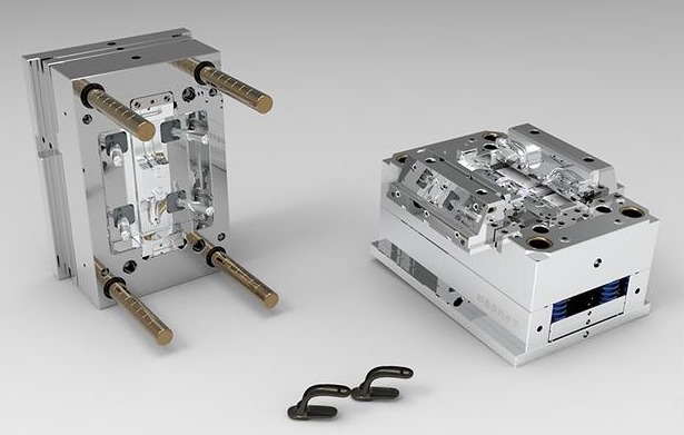
Mold Design
Mold design directly determines product quality. Any system such as gate setting, product layout, runner setting, cooling system, gate system, and supporting mold system may cause product defects.
- Gate design: The location, size, shape, and quantity of the gate will all affect the flow and filling effect of the plastic. Proper gate design helps achieve uniform filling and reduces flow resistance, increasing the probability of success.
- Product layout: Arrange products reasonably in the mold to ensure uniform injection pressure and temperature distribution and reduce problems such as deformation and color difference.
- Runner System: The Runner system should avoid direct punching as much as possible and allow the melt to flow along the contour of the mold, thus avoiding defects such as ejection.
- Cooling system: An effective cooling system can ensure that the plastic is cooled evenly in the mold, reducing uneven shrinkage and deformation.
- Mold materials and maintenance: Choose right high-quality mold materials and perform regular mold maintenance and upkeep to ensure the accuracy and life of the mold.
Mold machining
- Mold Tolerance: The processing accuracy of the mold directly affects the quality of injection molded parts. High-precision molds can reduce the occurrence of defects such as burrs and flash edges.
- Mold material selection: According to the use environment and performance requirements of the product, select appropriate mold materials to ensure the strength, wear resistance and life of the mold.
Injection Equipment
- Injection equipment selection: Choose an injection molding machine suitable for product production to ensure precise control of injection pressure, speed and position.
- Equipment maintenance: Regularly maintain and maintain the injection molding machine to ensure the accuracy and stability of the equipment.
- Equipment calibration: Regularly calibrate the temperature, pressure, speed and other parameters of the injection molding machine to ensure the stability and consistency of the production process
Injection Proecess
- Injection pressure and injection speed: Too fast an injection speed may cause bubbles, flow marks and other defects; too slow an injection speed may cause insufficient filling. Therefore, it is necessary to select the appropriate injection pressure and speed according to the properties of the plastic and the mold structure.
- Melt temperature: If the melt temperature is too high, it may cause the plastic to decompose and generate bubbles; if it is too low, it may cause problems such as insufficient filling and flow marks. Therefore, the melt temperature needs to be strictly controlled within an appropriate range.
- Mold temperature: If the mold temperature is too high, it may cause the plastic to solidify prematurely in the mold and produce internal stress; if it is too low, it may cause problems such as insufficient filling and uneven shrinkage. Therefore, the appropriate mold temperature needs to be selected based on the properties of the plastic and the mold structure.
Conclusion
Injection molding looks very simple at first glance, but it is not. In order to effectively avoid injection molding defects, it is necessary to comprehensively consider multiple aspects such as design, raw materials, molds, equipment and processes. Through reasonable part design, proven mold design solutions, precise mold machining, advanced injection molding equipment, precise process parameter settings and regular maintenance and upkeep, the occurrence of injection molding defects can be effectively reduced and product quality and production improved efficiency.