Surface roughness is an important consideration in manufacturing. It not only affects the product’s appearance and tactile feel, but also directly relates to the product’s performance and lifespan. Properly understanding and controlling surface roughness is significantly meaningful for improving product quality and reducing production costs.
This article will introduce in detail the concepts, parameters, measurement methods and control methods of surface roughness to help you better understand this key technical index.
What Is Surface Roughness?
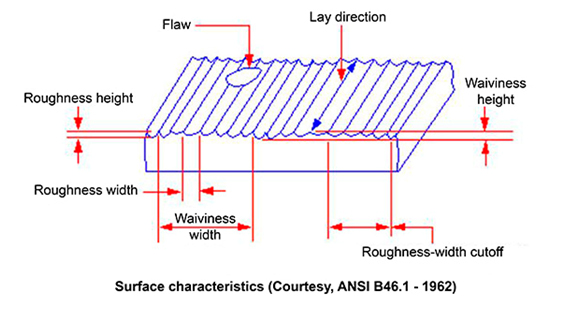
“Surface Roughness” in manufacturing typically refers to the degree of irregularity of the surface of an object. It is an important physical parameter used to describe the non-planarity, micro elevations and depressions, and texture characteristics of an object’s surface.
How is surface roughness formed?
The surface roughness is generally determined by the manufacturing process employed, material used and other factors. For example, friction between the tool and workpiece surface during CNC machining, surface metal layer warpage when chips are separated, and high-frequency vibration in the processing system. Due to differences in manufacturing processes, workpiece materials, and machining speed, the depth, density, shape and texture of traces left on the machined product surface vary.
Surface Roughness Parameters
The most common Surface Roughness Parameters include:
- Traversing Length
- Assessment Length
- Sampling Length
- Mean Line of the profile
- Rz (maximum average height of the profile)
- Rp (Maximum Profile Peak Height)
- Rv (Maximum Profile Valley Depth)
- Rmax (vertical distance from peak to the lowest valley)
- RMS (Root Mean Square)
- CLA (Center Line Average)
Why is Surface Finish/Roughness Important in Manufacturing Processes?
Surface roughness is very important for many manufacturing applications because it affects the friction, wear, optical properties, sealing properties, fatigue life, etc. of objects, and has a significant impact on product service life and reliability. In mechanical processing, controlling and improving surface roughness is one of the important means to enhance product quality and performance.
The following are the impacts of surface roughness on manufacturing:
1) Corrosion Resistance
The micro pits on the rough surfaces of parts easily allow corrosive gases or liquids to penetrate into the inner metal layers, resulting in surface corrosion. Therefore, reducing surface roughness helps improve parts’ corrosion resistance.
2) Sealing Performance
Surface roughness directly affects the sealing performance of parts. Rough surfaces cannot tightly fit together, making gases or liquids more likely to leak through gaps between contact surfaces. Optimizing surface roughness helps improve parts’ sealing performance.
3) Functional Requirements
The functions and performances of many products are directly affected by surface roughness. For example, in automotive manufacturing, surface roughness of parts influence their friction coefficient, sealing performance and fatigue life. In optical instrument manufacturing, surface roughness affects light refraction and reflection, thus influencing the precision of instruments.
4) Production Costs
Higher surface roughness usually requires more machining time and effort, increasing production costs. Controlling surface roughness can improve production efficiency and reduce costs.
5) Product Quality
Surface roughness is one of the key indicators to measure product quality. Lower surface roughness can enhance product appearance quality and service life, improving its market competitiveness.
6) Assembly Precision
The fitting precision between parts during assembly is directly affected by surface roughness. Controlling surface roughness can improve assembly precision, reduce gaps and errors between parts. Optimizing surface roughness helps ensure the stability and reliability of parts fitting.
7) Fatigue Strength
Surface roughness generates stress concentration points on part surfaces, reducing fatigue strength. Controlling surface roughness can minimize stress concentration phenomenon, improve part fatigue strength and reduce the risk of fatigue failure.
How to Measure Surface Roughness?
Parameter Ra is one way to quantify surface roughness. There are various common methods to measure surface roughness. The main types of measurement techniques include direct measurement, comparative measurement, non-contact measurement and in-process measurement.
1) Contact Method
It performs the test by directly moving a fine probe stylus over the sample surface and recording the vertical movements of the sample surface irregularities to form a roughness profile graph. This method can provide relatively accurate measurement results but requires delicate operation to avoid damaging the surface.
2) Non-contact Method
Non-contact methods mainly use optical, acoustic or electromagnetic principles to measure surface roughness without direct contact with the measured surface.
- Optical interferometry:Leverage the interference of light to measure the micro-unevenness of a surface. The roughness parameters can be deduced by observing the changes of interference fringes. This method has high measurement accuracy but the equipment cost is also higher, and it has certain requirements on the operating environment.
- Laser scanning: A laser beam scans the measured surface, and the roughness is measured by collecting and analyzing the information of the reflected light. This method has advantages of non-contact, fast, and high precision, suitable for measuring large areas or complex shapes surfaces.
3) Comparison Method
Comparative methods involve comparing the measured surface with a standard sample of known roughness to judge the roughness of the measured surface
Visual comparative method: Use the naked eye or magnifying glass to observe the differences between the measured surface and the standard sample, and evaluate the surface roughness through comparison. This method is simple to implement but is greatly affected by human factors and low in accuracy.
Tactile comparative method: Judge the roughness by touching the measured surface. This method relies on the operator’s experience and also has the problem of low accuracy.
4) In-process Method
In-process methods generally refer to methods of directly measuring surface roughness during production, mainly for real-time monitoring of product quality.
Special surface roughness measuring instruments are usually installed on the production line to realize real-time measurement of products during the production process. This method can detect surface roughness issues of products in a timely manner so that production processes can be adjusted promptly to ensure product quality.
Measure Surface Roughness Methods
There are two main methods for surface roughness measurement which are contact measurement and non-contact measurement. Surface roughness is usually measured using a surface roughness tester. Common measurement methods include stylus measurement, optical interferometry and laser scanning methods.
1. Contact-based measurement: Contact Profilometer
Contact surface roughness measurement directly contacts the measuring instrument’s stylus with the measured surface. By the minute displacement of the stylus, it reflects the contour variation of the measured surface to obtain relevant information about surface roughness.
Advantages of Contact–based Surface Roughness Measurement
- High accuracy: Contact measurement can provide high measurement accuracy, especially in the medium-highroughness range.
- Direct measurement: The stylus directly contacts the measured surface to directly obtain the shape and roughness information of the surface.
- Wide applicability: Contact measurement is applicable to surfaces of various materials and shapes, including plane, curve and complex shapes.
- Low cost: Compared with non-contact measurement methods, the cost of contact measurement equipment is generally lower.
- Mature algorithms and high measurement accuracy: Direct contact with the measured surface results in high accuracy.
Disadvantages of Contact–based Surface Roughness Measurement
- Surface scratching and damage:Contact measurement can cause certain scratches or damage to the measured surface during the measurement process, especially for high-precision surfaces and soft metal surfaces, where the damage is more obvious.
- Limitation in measurement accuracy:Due to the limitation of the stylus tip radius, the accuracy of contact measurement may be affected, especially when measuring low-roughness surfaces.
- Easy wear and deformation of stylus:The stylus may wear or deform during the measurement process, affecting the measurement accuracy. Regular stylus replacement or calibration is needed.
- Slower measurement speed:Compared with non-contact measurement methods, the speed of contact measurement is generally slower, not suitable for fast measurement.
2. Non-contact Measurement: Optical Interferometry
Non-contact surface roughness measurement is a measurement method that can detect surface roughness without direct contact with the measured surface. It can avoid damage or deformation to the surface. The following are some common methods of non-contact surface roughness measurement:
- Optical interferometer: Its working principle is based on the wave nature of light and the principle of optical interference. It utilizes the superposition of two or multiple light waves in space, generating interference fringes of alternating light and dark, and further obtains information about physical quantities of the measured object such as shape, size and refractive index through measuring and analyzing these interference fringes.
- Laser scanning microscope: It uses a laser beam to scan the measured surface, and determines the roughness of the surface by measuring the intensity of the reflected light. This method can provide high-resolution measurement results.
- Atomic force microscope (ASM): It determines the roughness of the surface by measuring the interaction forces between the probe and the measured surface. This method can provide extremely high resolution but usually requires measurement in a laboratory environment.
- Optical profiler: It uses optical methods to measure the contour of the surface to determine the roughness of the surface. This method is suitable for measuring surfaces of relatively large sizes.
- Confocal microscope: It uses the confocal principle to measure the roughness of the surface. By focusing a laser beam on the measured surface and measuring the intensity of the reflected light, it determines the roughness of the surface.
Advantages of Non-contact Surface Roughness Measurement
- Non-destructive measurement: It does not require contact with the measured surface, avoiding damage or deformation to the surface, suitable for measuring soft, fragile or high-precision surfaces.
- Fast and efficient: The measurement speed is fast, enabling real-time measurement suitable for online monitoring and quick detection in production processes.
- High-precision measurement: Based on advanced optical, laser or computer vision technologies, it can provide high-resolution measurement results meeting precision requirements for surface measurement.
- Suitable for complex shapes: It can easily handle complex shapes or surfaces that are difficult to contact, including three-dimensional curved surfaces, irregular shapes and small holes.
Disadvantages of Non-contact Surface Roughness Measurement
- Higher requirements for the environment: Non-contact measurement methods are usually more sensitive to vibration, temperature, humidity and other environmental conditions, requiring measurement in a stable environment.
- Higher costs: Compared with contact measurement methods, non-contact measurement equipment generally costs more.
- Limitations for reflective surfaces: Non-contact measurement methods place higher demands on reflective surfaces, and may not be able to perform accurate measurements on surfaces with low reflectivity or non-specular reflection.
- Limited measurement range: The measurement range of non-contact measurement methods is generally smaller and not suitable for large-scale surface measurement.
- More difficult to process edges, holes and discontinuous shapes: For certain specific surface features such as edges, holes and discontinuous shapes, non-contact measurement may have difficulty obtaining accurate measurement data.
Surface Roughness Chart Symbols
When drawing engineering drawings, the surface finish of flat and circular surfaces is represented as follows:
For flat surfaces
For round surfaces
Surface finish call-out
Surface finish call-out refers to the clear description of the surface roughness requirements of the part in engineering drawings or technical specifications. You can add the following symbols to drawings.
How to fill in the “a”, “f” and “I” values of the above symbols, you can fill in the following table according to the surface roughness requirements of the specific product.
Surface Roughness Terminology
Ra (Average Surface Roughness)
Ra is a parameter of surface roughness. It is the arithmetic average of the absolute values of the roughness profile deviations from the mean line within the evaluation length. The smaller the Ra value, the smoother the surface; the larger the Ra value, the rougher the surface. The value of Ra is usually expressed in units of microns (μm).
Rz (maximum average height of the profile)
Rz is a parameter of surface roughness. It represents the sum of the average value of the five highest profile peaks and the average value of the five deepest profile valleys within the sampling length.
This parameter is mainly used to describe the degree of surface irregularity. Specifically, Rz is obtained by first finding the five highest profile peaks and five deepest profile valleys within a specified sampling length, then respectively calculating the average heights of these peaks and valleys, and finally summing the two average values.
This parameter provides an overall assessment of surface roughness, especially when there are significant fluctuations. It is worth noting that Rz is only one parameter of surface roughness and cannot completely describe all characteristics of the surface. Compared to Ra, Rz places more emphasis on the height information of peaks and valleys, and is more sensitive to surfaces with obvious profiles. The lower the Rz value, the smoother the surface; the higher the Rz value, the rougher the surface.
Rp (Maximum Profile Peak Height)
Rp describes the height of the highest peaks on the surface. It reflects the degree of local convexity of the surface. The larger the Rp value, the more prominent the peaks on the surface; the smaller the Rp value, the flatter the surface.
Rp is a parameter of surface roughness. It refers to the maximum value of the distance from the profile peak tops to the reference line within a sampling length. This parameter is mainly used to describe the maximum peak height of the surface profile, i.e. the distance between the highest point and the reference line on the surface.
If the Rp is large, it means that the surface has relatively high peak tops, which may affect the performance and function of the surface, such as friction, wear and sealing. Therefore, in some applications with high requirements for surface roughness, special attention needs to be paid to and control of the Rp is needed. Engineering drawings or technical specifications may specify the required range of Rp to ensure that the quality of the surface of parts meets design requirements.
Rv (Maximum Profile Valley Depth)
Much like Rp, Rv refers to the maximum value of the distance from the profile valley bottoms to the reference line within a sampling length. This parameter is mainly used to describe the maximum valley depth of the surface profile, i.e. the distance between the lowest point and the reference line on the surface.
The larger the Rv, the more prominent the deep valleys on the surface; the smaller the Rv, the flatter the surface. The magnitude of the Rv can reflect the depth of the valleys on the surface, helping us understand the degree of surface irregularity. If the Rv value is large, it means that the surface has relatively deep valleys, which may affect the frictional, wear and sealing performance of the surface. Applications with strict surface quality requirements need to pay attention to and control the Rv.
Rmax (vertical distance from peak to the lowest valley)
Rmax refers to the distance between the maximum profile peak height and maximum profile valley depth within the sampling length. It directly reflects the maximum height difference of the surface profile. The larger the Rmax value, the rougher the surface; the smaller the Rmax value, the smoother the surface.
The magnitude of the Rmax value has a direct impact on the frictional, wear and sealing performance of the surface. A larger Rmax value means that the surface has significant undulations, which could increase frictional resistance, reduce wear resistance, and even affect sealing effect.
RMS (Root Mean Square)
In surface roughness measurement, RMS (Root Mean Square) usually refers to “Root Mean Square Roughness”. RMS is derived by calculating the root mean square of the surface height distribution data. Specifically, it involves squaring each value of the surface height data, then taking the average, and finally taking the square root. This result can reflect the overall fluctuation of the surface height, including information of peaks and valleys.
A lower RMS value indicates a smoother surface, while a higher RMS value indicates a rougher surface.
CLA (Center Line Average)
CLA mean is Center Line Average. CLA (Center Line Average) represents the arithmetic average of the profile heights along the center line within a specified length.
Typically, a set of profile points are selected as the sampling length and the height deviations of these points relative to the center line are measured. Then, the absolute values of these deviation values are taken and their arithmetic average is calculated, resulting in the CLA value.
A smaller CLA value indicates a smoother surface, while a larger CLA value indicates a rougher surface.
RMS vs Ra
RMS and Ra parameters are related when describing surface roughness, but their calculation methods are different. Ra is obtained by averaging the absolute values of the deviations of the surface heights from the mean line, while RMS is obtained by calculating the root mean square of the surface heights.
Units of Measurement for Surface Roughness
There are many parameters for measuring surface roughness, but arithmetical mean roughness (Ra) is universally recognized as the most common measurement standard. Ra is calculated in micrometers (μm) or microinches (μin.). The smaller the Ra value, the smoother the surface; the larger the Ra value, the rougher the surface.
Surface Roughness Chart
Surface finish chart (also called surface roughness chart) is a graphical representation method for surface roughness. It is used to demonstrate the visual characteristics of surfaces at different roughness levels. This type of chart typically includes a series of sample images or schematic diagrams of different roughness levels to intuitively understand the differences between different roughness levels.
How to use a surface roughness comparator?
Look below video you’ll understand.
How to Choose the Suitable Surface Roughness for Your Project?
The selection of an appropriate surface roughness depends on multiple factors, including the application field, functional requirements, material type and manufacturing process. Here are some general guidelines for choosing a surface roughness:
1) Application field
Different application fields have different requirements for surface roughness. For example, a lower surface roughness can improve the precision and wear resistance of high-precision mechanical parts, while a higher roughness may increase the aesthetics of some consumer products.
2) Functional requirements
Choose the surface roughness according to the functional requirements of the part. For example, an appropriate roughness can provide good lubrication for parts that require sliding fits, while a lower roughness can improve the sealing performance of parts that require sealing.
3) Materials
Different materials have different requirements for surface roughness. Some materials like plastics and rubbers may require a higher roughness to improve adhesion, while lower roughness can reduce friction and wear for metal materials.
4) Manufacturing process
The choice of surface roughness also needs to consider the limitations of the manufacturing process. Some processes may not achieve a very low surface roughness, so a suitable grade within the feasible range should be selected.
5) Cost-effectiveness
A lower surface roughness usually requires more complex processing and higher costs. So the relationship between cost and performance needs to be balanced when selecting roughness.
6) Consider fitting properties
For fitting surfaces such as shafts and holes, the roughness should be selected according to the fitting properties and requirements. For clearance fits, the smaller the clearance gap, the smaller the roughness value should be; for interference fits, to ensure robust and reliable connection, the larger the load, the smaller the roughness value is required.
7) Consider dimensional and shape tolerances
Generally, the surface roughness value of a smaller sized part should be smaller than that of a larger part within the same precision grade. In addition, the roughness of the fitting surface should correspond to its dimensional accuracy requirements.
8) Consider stress concentration and periodic loading
For structures prone to stress concentration (such as fillets, grooves, etc.) and surfaces subject to periodic loads, a smaller roughness value should be selected to improve the strength and durability of the part.
What are the Factors Affecting Surface Finishes?
1) Operating skills
The technical skills and experience of the operator are also important factors affecting surface roughness. Improper operation or lack of technical proficiency may lead to failure to meet surface roughness standards.
2) Machining parameters
Cutting speed, feed rate, cutting depth and other machining parameters will affect the friction and cutting force between the tool and the workpiece, thereby affecting the surface quality.
3) Material
Different materials have great differences in hardness, toughness and wear resistance. These characteristics will affect the smoothness of the machined surface. In addition, material quality also has an important impact on surface finish.
4) Machining environment
Dust, dirt and other external environmental factors may leave traces on the product surface, affecting the surface surface. For example, the temperature and humidity inside the production workshop cannot be ignored.
5) Coolant
The type, flow rate and spraying method of the coolant will affect the heat exchange and lubrication between the tool and the workpiece, thereby affecting the surface roughness.
6) Machine tool accuracy
The accuracy and stability of the machine tool will affect the surface roughness of the machined surface.
7) Tool path
The planning and programming of the tool path will affect the surface roughness of the machined surface.
8) Machining environment
Dust, dirt and other external environmental factors may leave traces on the product surface, affecting the surface surface. For example, the temperature and humidity inside the production workshop can’t be ignored.
9) Machining method
Different machining methods such as turning, milling, laser processing, etc. can achieve different surface precision.
10) Tool performance
The material, shape, sharpness and wear of the tool will affect the surface roughness of the machined surface.
11) Machining equipment performance
The motion accuracy and rigidity of the CNC machine tool will affect the surface quality.
12) Post-processing
Processes such as grinding and polishing can improve surface roughness, but are prone to non-uniformity.
13) Workpiece structure
The degree of unevenness on the surface will also affect the final roughness.
What is the Average Surface Roughness of CNC Machining?
The surface roughness achieved through CNC machining can vary depending on multiple factors, including the workpiece material, cutting tool, cutting speed, feed rate and depth of cut.
Generally, CNC machining of steel can achieve a surface roughness in the range of Ra 0.8-1.6 μm, and CNC machining of aluminum can achieve a surface roughness in the range of Ra 0.2-0.8 μm.
Generally, the surface roughness range achieved through CNC turning is 0.8~1.6μm. For rough turning, the required surface roughness is 20-10μm; for semi-precision turning and precision turning, the required surface roughness is 10-0.16μm. Using diamond grinding tools to perform high-speed precision hard turning of non-ferrous metal workpieces can achieve a surface roughness of 0.04-0.01μm, which is also known as “mirror surface turning”.
The surface roughness from CNC milling is generally 6.3-1.6μm. For rough milling, the surface roughness is 20-5μm, for semi-precision milling it is 10-2.5μm, and for precision milling it is 6-0.63μm.
These values only represent approximate ranges and do not mean that all CNC machining can achieve these levels. Actual machining should adjust and optimize according to specific requirements and conditions to achieve optimal machining results.
The following is the summary
CNC Milling: 63 μin (1.6 μm) to 32 μin (0.8 μm)
CNC Turning: 32 μin (0.8 μm) to 16 μin (0.4 μm)
CNC Drilling:16 μin (0.4 μm) 至 8 μin (0.2 μm)
CNC EDM:4 μin (0.1 μm) 至 1.25 μin (0.03 μm)
CNC ECM:2.5 μin (0.0625 μm) 至 1.25 μin (0.03 μm)
Surface Roughness Comparison Table in Different Countries
The most comprehensive surface roughness comparison table for machining processes
Material and manufacturing process are the main factors that determine the level of surface roughness. The following table lists the minimum and maximum surface roughness values of common machining processes for reference.
见表格:The most comprehensive surface roughness comparison table for machining processes
Surface Roughness Conversion Chart
下表格是表面光洁度换算表。该表比较了制造工艺的不同表面粗糙度等级之间的换算。
表格见excel表Surface Roughness Conversion Chart
Ra = Roughness Average
RMS = Root Mean Square
CLA = Center Line Average
Rt = Roughness Total
N = New ISO (Grade) Scale Numbers
Cut-off Length = Length Required for Sample
Surface Roughness Chart Cheat Sheet
Surface roughness chart cheat sheet can help you quickly reference and compare different surface roughness levels and their corresponding characteristics. The actual surface roughness levels and values may vary due to different standards and applications. The translation retains the original meaning without any changes.
表格见excel表Surface Roughness Chart Cheat Sheet
Conclusion
Surface roughness refers to the irregularities of small spacing and minor peaks and valleys on a machined surface. It has significant impacts on the performance and lifespan of parts. Selecting an appropriate surface roughness can improve part precision, wear resistance, sealing performance and other qualities, while also reducing production costs. In the design and manufacturing process, material, process and cost factors need to be comprehensively considered to reasonably control the surface roughness. If you have any questions regarding surface finish or surface roughness, please contact us now.